Basics
What are the different service group types ?
Service groups can be one of the 3 type :
1. Failover – Service group runs on one system at a time.
2. Parallel – Service group runs on multiple systems simultaneously.
3. Hybrid – Used in replicated data clusters (disaster recovery setups). SG behaves as Failover within the local cluster and Parallel for the remote cluster.
1. Failover – Service group runs on one system at a time.
2. Parallel – Service group runs on multiple systems simultaneously.
3. Hybrid – Used in replicated data clusters (disaster recovery setups). SG behaves as Failover within the local cluster and Parallel for the remote cluster.
Where is the VCS main configuration file located ?
The main.cf file contains the configuration of the entire cluster and is located in the directory/etc/VRTSvcs/conf/config.
How to set VCS configuration file (main.cf) ro/rw ?
To set the configuration file in read-only/read-write :
# haconf -dump -makero     (Dumps in memory configuration to main.cf and makes it read-only)
# haconf -makerw           (Makes configuration writable)
Where is the VCS engine log file located ?
The VCS cluster engine logs is located at /var/VRTSvcs/log/engine_A.log. We can either directly view this file or use command line to view it :
# hamsg engine_A
How to check the complete status of the cluster
To check the status of the entire cluster :
# hastatus -sum
How to verify the syntax of the main.cf file
To verify the syntax of the main.cf file just mention the absolute directory path to the main.cf file :
# hacf -verify /etc/VRTSvcs/conf/config
What are the different resource types ?
1. Persistent : VCS can only monitor these resources but can not offline or online them.
2. On-Off : VCS can start and stop On-Off resource type. Most resources fall in this category.
3. On-Only : VCS starts On-Only resources but does not stop them. An example would be NFS daemon. VCS can start the NFS daemon if required, but can not take it offline if the associated service group is take offline.
Explain the steps involved in Offline VCS configuration
1. Save and close the configuration :
# haconf -dump -makero
2. Stop VCS on all nodes in the cluster :
# hastop -all
3. Edit the configuration file after taking the backup and do the changes :
# cp -p /etc/VRTSvcs/conf/config/main.cf /etc/VRTSvcs/conf/config/main.cf_17march
# vi /etc/VRTSvcs/conf/config/main.cf
4. Verify the configuration file syntax :
# hacf -verify /etc/VRTSvcs/conf/config/
5. start the VCS on the system with modified main.cf file :
# hastart
6. start VCS on other nodes in the cluster.
Note : This can be done in another way by just stopping VCS and leaving services running to minimize the downtime. (hastop -all -force
GAB, LLT and HAD
What is GAB, LLT and HAD and whats their functionalities ?
GAB, LLT and HAD forms the basic building blocks of vcs functionality.
LLT (low latency transport protocol) – LLT transmits the heartbeats over the interconnects. It is also used to distribute the inter system communication traffic equally among all the interconnects.
GAB (Group membership services and atomic broadcast) – The group membership service part of GAB maintains the overall cluster membership information by tracking the heartbeats sent over LLT interconnects. The atomic broadcast of cluster membership ensures that every node in the cluster has same information about every resource and service group in the cluster.
HAD (High Availability daemon) – the main VCS engine which manages the agents and service group. It is in turn monitored by a daemon named hashadow.
What are the various GAB ports and their functionalities ?
a  -->     gab driver
b  -->     I/O fencing (to ensure data integrity)
d  -->     ODM (Oracle Disk Manager)
f  -->     CFS (Cluster File System)
h  -->     VCS (VERITAS Cluster Server: high availability daemon, HAD)
o  -->     VCSMM driver (kernel module needed for Oracle and VCS interface)
q  -->     QuickLog daemon
v  -->     CVM (Cluster Volume Manager)
w  -->     vxconfigd (module for cvm)
How to check the status of various GAB ports on the cluster nodes
To check the status of GAB ports on various nodes :
# gabconfig -a
Whats the maximum number of LLT links (including high and low priority) can a cluster have ?
A cluster can have a maximum of 8 LLT links including high and low priority LLT links.
How to check the detailed status of LLT links ?
The command to check detailed LLT status is :
# lltstat -nvv
What are the various LLT configuration files and their function ?
LLT uses /etc/llttab to set the configuration of the LLT interconnects.
# cat /etc/llttab
set-node node01
set-cluster 02
link nxge1 /dev/nxge1 - ether - -
link nxge2 /dev/nxge2 - ether - -
link-lowpri /dev/nxge0 – ether - -
Here, set-cluster -> unique cluster number assigned to the entire cluster [ can have a value ranging between 0 to (64k – 1) ]. It should be unique across the organization.
set-node -> a unique number assigned to each node in the cluster. Here the name node01 has a corresponding unique node number in the file /etc/llthosts. It can range from 0 to 31.
set-node -> a unique number assigned to each node in the cluster. Here the name node01 has a corresponding unique node number in the file /etc/llthosts. It can range from 0 to 31.
Another configuration file used by LLT is – /etc/llthosts. It has the cluster-wide unique node number and nodename as follows:
# cat /etc/llthosts
0 node01
1 node02
LLT has an another optional configuration file : /etc/VRTSvcs/conf/sysname. It contains short names for VCS to refer. It can be used by VCS to remove the dependency on OS hostnames.
What are various GAB configuration files and their function ?
The file /etc/gabtab contains the command to start the GAB.
# cat /etc/gabtab
/sbin/gabconfig -c -n 4
here -n 4 –> number of nodes that must be communicating in order to start VCS.
How to start/stop GAB
The commands to start and stop GAB are :
# gabconfig -c        (start GAB)
# gabconfig -U        (stop GAB)
How to start/stop LLT
The commands to stop and start LLT are :
# lltconfig -c       -> start LLT
# lltconfig -U       -> stop LLT (GAB needs to stopped first)
What’s a GAB seeding and why manual GAB seeding is required ?
The GAB configuration file /etc/gabtab defines the minimum number of nodes that must be communicating for the cluster to start. This is called as GAB seeding.
In case we don’t have sufficient number of nodes to start VCS [ may be due to a maintenance activity ], but have to do it anyways, then we have do what is called as manual seeding by firing below command on each of the nodes.
In case we don’t have sufficient number of nodes to start VCS [ may be due to a maintenance activity ], but have to do it anyways, then we have do what is called as manual seeding by firing below command on each of the nodes.
# gabconfig -c -x
How to start HAD or VCS ?
To start HAD or VCS on all nodes in the cluster, the hastart command need to be run on all nodes individually.
# hastart
What are the various ways to stop HAD or VCS cluster ?
The command hastop gives various ways to stop the cluster.
# hastop -local
# hastop -local -evacuate
# hastop -local -force
# hastop -all -force
# hastop -all
Resource Operations
How to list all the resource dependencies
To list the resource dependencies :
# hares -dep
How to enable/disable a resource ?
# hares -modify [resource_name] Enabled 1      (To enable a resource)
# hares -modify [resource_name] Enabled 0        (To disable a resource)
How to list the parameters of a resource
To list all the parameters of a resource :
# hares -display [resource]
Service group operations
How to add a service group(a general method) ?
In general, to add a service group named SG with 2 nodes (node01 and node02) :
haconf –makerw
hagrp –add SG
hagrp –modify SG SystemList node01 0 node02 1
hagrp –modify SG AutoStartList node02
haconf –dump -makero
How to check the configuration of a service group – SG ?
To see the service group configuration :
# hagrp -display SG
How to bring service group online/offline ?
To online/offline the service group on a particular node :
# hagrp -online [service-group] -sys [node]      (Online the SG on a particular node)
# hagrp -offline [service-group] -sys [node]        (Offline the SG on particular node)
The -any option when used instead of the node name, brings the SG online/offline based on SG’s failover policy.
# hagrp -online [service-group] -any
# hagrp -offline [service-group] -any
How to switch service groups ?
The command to switch the service group to target node :
# hagrp -switch [service-group] -to [target-node]
How to freeze/unfreeze a service group and what happens when you do so ?
When you freeze a service group, VCS continues to monitor the service group, but does not allow it or the resources under it to be taken offline or brought online. Failover is also disable even when a resource faults. When you unfreeze the SG, it start behaving in the normal way.
To freeze/unfreeze a Service Group temporarily :
# hagrp -freeze [service-group]
# hagrp -unfreeze [service-group]
To freeze/unfreeze a Service Group persistently (across reboots) :
# hagrp -freeze -persistent[service-group]
# hagrp -unfreeze [service-group] -persistent
Communication failures : Jeopardy, split brain
Whats a Jeopardy membership in vcs clusters
When a node in the cluster has only the last LLT link intact, the node forms a regular membership with other nodes with which it has more than one LLT link active and a Jeopardy membership with the node with which it has only one LLT link active.
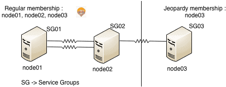
Effects of jeopardy : (considering example in diagram above)
1. Jeopardy membership formed only for node03
2. Regular membership between node01, node02, node03
3. Service groups SG01, SG02, SG03 continue to run and other cluster functions remain unaffected.
4. If node03 faults or last link breaks, SG03 is not started on node01 or node02. This is done to avoid data corruption, as in case the last link is broken the nodes node02 and node01 may think that node03 is down and try to start SG03 on them. This may lead to data corruption as same service group may be online on 2 systems.
5. Failover due to resource fault or operator request would still work.
How to recover from a jeopardy membership ?
To recover from jeopardy, just fix the failed link(s) and GAB automatically detects the new link(s) and the jeopardy membership is removed from node.
Whats a split brain condition ?
Split brain occurs when all the LLT links fails simultaneously. Here systems in the cluster fail to identify whether it is a system failure or an interconnect failure. Each mini-cluster thus formed thinks that it is the only cluster thats active at the moment and tries to start the service groups on the other mini-cluster which he think is down. Similar thing happens to the other mini-cluster and this may lead to a simultaneous access to the storage and can cause data corruption.
What is I/O fencing and how it prevents split brain ?
VCS implements I/O fencing mechanism to avoid a possible split-brain condition. It ensure data integrity and data protection. I/O fencing driver uses SCSI-3 PGR (persistent group reservations) to fence off the data in case of a possible split brain scenario.

In case of a possible split brain
As show in the figure above assume that node01 has key “A” and node02 has key “B”.
1. Both nodes think that the other node has failed and start racing to write their keys to the coordinator disks.
2. node01 manages to write the key to majority of disks i.e. 2 disks
3. node02 panics
4. node01 now has a perfect membership and hence Service groups from node02 can be started on node01
Whats the difference between MultiNICA and MultiNICB resource types ?
MultiNICA and IPMultiNIC
– supports active/passive configuration.
– Requires only 1 base IP (test IP).
– Does not require to have all IPs in the same subnet.
– supports active/passive configuration.
– Requires only 1 base IP (test IP).
– Does not require to have all IPs in the same subnet.
MultiNICB and IPMultiNICB
– supports active/active configuration.
– Faster failover than the MultiNICA.
– Requires IP address for each interface.
– supports active/active configuration.
– Faster failover than the MultiNICA.
– Requires IP address for each interface.
Troubleshooting
How to flush a service group and when its required ?
Flushing of a service group is required when, agents for the resources in the service group seems suspended waiting for resources to be taken online/offline. Flushing a service group clears any internal wait states and stops VCS from attempting to bring resources online.
To flush the service group SG on the cluster node, node01 :
# hagrp -flush [SG] -sys node01
How to clear resource faults ?
To clear a resource fault, we first have to fix the underlying problem.
1. For persistent resources :
Do not do anything and wait for the next OfflineMonitorInterval (default – 300 seconds) for the resource to become online.
Do not do anything and wait for the next OfflineMonitorInterval (default – 300 seconds) for the resource to become online.
2. For non-persistent resources :
Clear the fault and probe the resource on node01 :
Clear the fault and probe the resource on node01 :
# hares -clear [resource_name] -sys node01
# hares -probe [resource_name] -sys node01
How to clear resources with ADMIN_WAIT state ?
If the ManageFaults attribute of a service group is set to NONE, VCS does not take any automatic action when it detects a resource fault. VCS places the resource into the ADMIN_WAIT state and waits for administrative intervention.
1. To clear the resource in ADMIN_WAIT state without faulting service group :
# hares -probe [resource] -sys node01
2. To clear the resource in ADMIN_WAIT state by changing the status to OFFLINE|FAULTED :
# hagrp -clearadminwait -fault [SG] -sys node01